Embedded and Low-Gain Communication Antenna Development
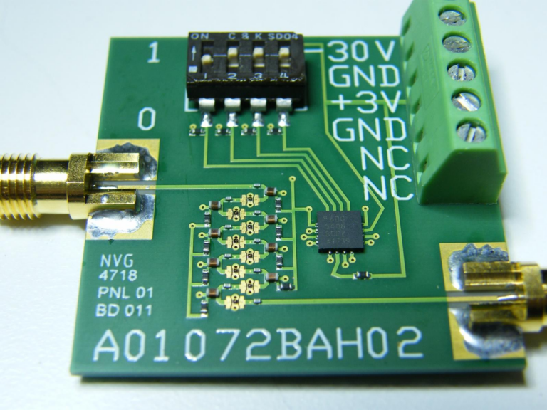
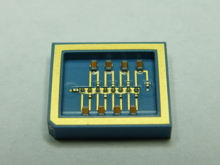
At Alpha Omega Electromagnetics, we have the expertise required to develop and deliver high performance embedded and low-gain antenna architectures for mobile, covert, and other applications requiring electrically small antennas for communication applications. AOE use its vast expertise in electromagnetic and mechanical modeling to integrate these antennas into their target packages and ensure that they operate optimally in their intended environment.
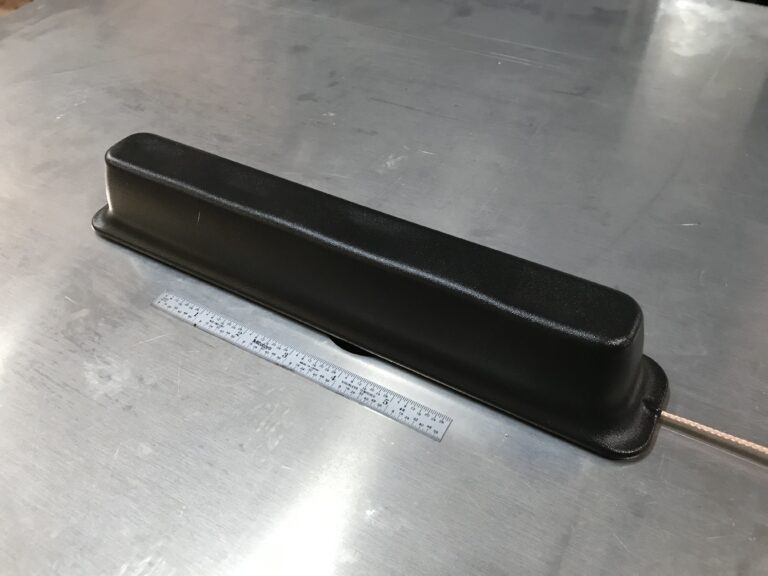
ORBCOMM Tri-Band Bar Antenna
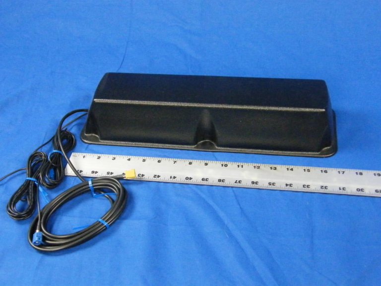
ORBCOMM Tri-Band Bar Antenna
- Designed for use on mobile platforms utilizing the ORBCOMM satellite network
- Three antenna elements integrated into one package
- ORBCOMM VHF antenna element
- Active GPS element
- Passive Cellular GSM/GPRD antenna that covers the 800/1700/1900/2100 MHz frequency band
ORBCOMM Tri-Band Bar Antenna Parameters – VHF Antenna Element
| Parameter | Requirement |
| Transmit frequency | 148.0000 – 150.0100 MHz |
| Receive frequency | 137.0000 – 138.0000 MHz |
| Operating Mode | Half Duplex |
| Transmit power | 10 W |
| VSWR transmit | 1.5:1 |
| VSWR receive | 2.0:1 |
| Impedance | 50 W |
| Minimum gain | -7 dBi |
| Elevation pattern | Optimize between 5° and 45° |
| Azimuth pattern | 360° |
| Size | Must fit within an enclosure that is 4” wide by 3” tall by 16” long, excluding mounting bosses |
| Polarization | RHCP desired |
| Cabling | 5m RG-58 cable with TNC/M connector |
| Temperature | -40°C to +85°C |
| Shock and Vibration | Per SAE J1455 for Chassis Mounted Equipment |
| Radome load bearing | 150 pound vertical load |
| Radome color | Black |
ORBCOMM Tri-Band Bar Antenna Parameters – GPS Antenna Element
| Parameter | Requirement |
| Frequency | 1575.42 ± 1.023 MHz |
| Configuration | Active antenna |
| Gain | -5 dBiC minimum at zenith |
| Axial ratio | 4.0 dB maximum at zenith |
| Polarization | RHCP |
| Size | Must fit within ORBCOMM antenna package |
| Cabling | 5m RG-174 cable with SMA/M connector |
| Temperature | -40°C to +85°C |
| Shock and Vibration | Per SAE J1455 for Chassis Mounted Equipment |
Compact, Low-Cost L-Band Antenna for Use with Inmarsat System
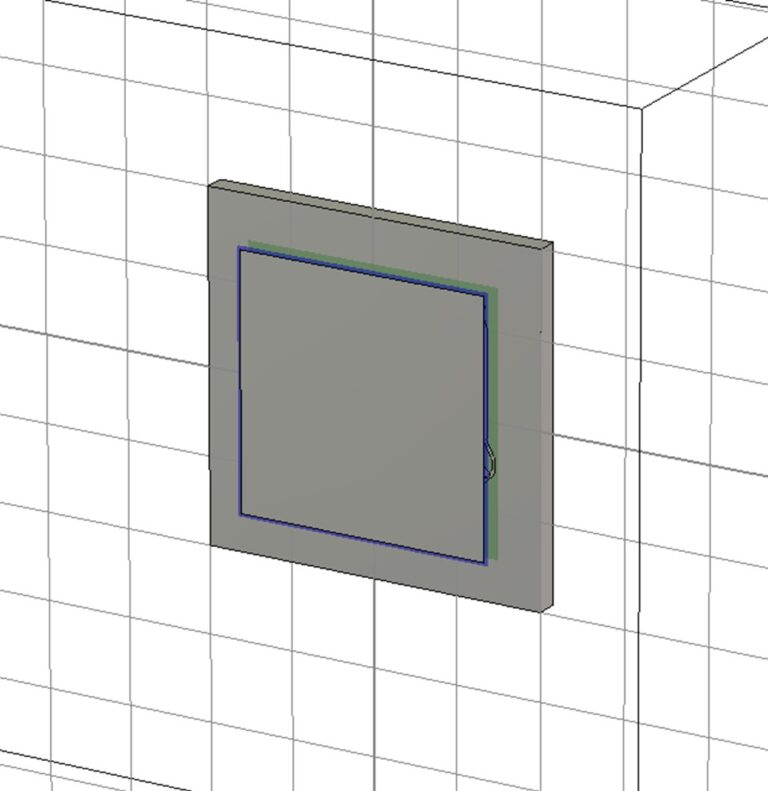
Table 1. Internal Printed Circuit Board Mounted L-Band Antenna design requirements
Parameter | Requirement |
Receive frequency | Extended band: 1518 – 1525 MHz Normal band: 1525 – 1559 MHz |
GPS frequency | 1575.52 MHz |
Transmit frequency | Normal band: 1626.5 – 1660.5 MHz Extended band: 1668 – 1675 MHz |
Polarization | RHCP |
Axial Ratio (at zenith) | < 6 dB @ 1518 – 1559 MHz < 3 dB @ 1575.42 MHz < 5 dB @ 1626.5 – 1660.5 MHz < 6 dB @ 1668 – 1675 MHz |
Gain (at zenith) | +1 dBic min @ 1518 – 1525 MHz +2 dBic min @ 1525 – 1559 MHz +2 dBic min@ 1575.42 MHz +3 dBic min @ 1626.5 – 1660.5 MHz +2 dBic min @ 1668 – 1675 MHz |
Nominal Impedance | 50 Ω |
VSWR | < 2.5:1 @ 1518 – 1559 MHz < 2.5:1 @ 1575.42 MHz < 1.8:1 @ 1626.5 – 1675 MHz |
Transmit Power | 2 W CW @ 1626.5 – 1660.5 MHz 2 W CW @ 1668 – 1675 MHz |
Size | Must less than or equal to 3” long by 3” wide by 0.25” tall |
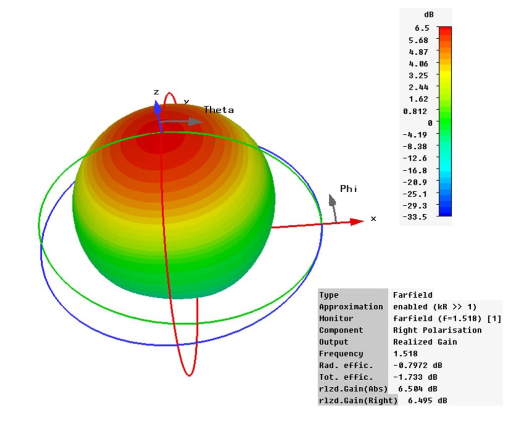
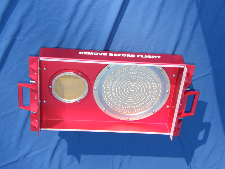
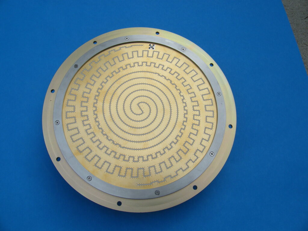
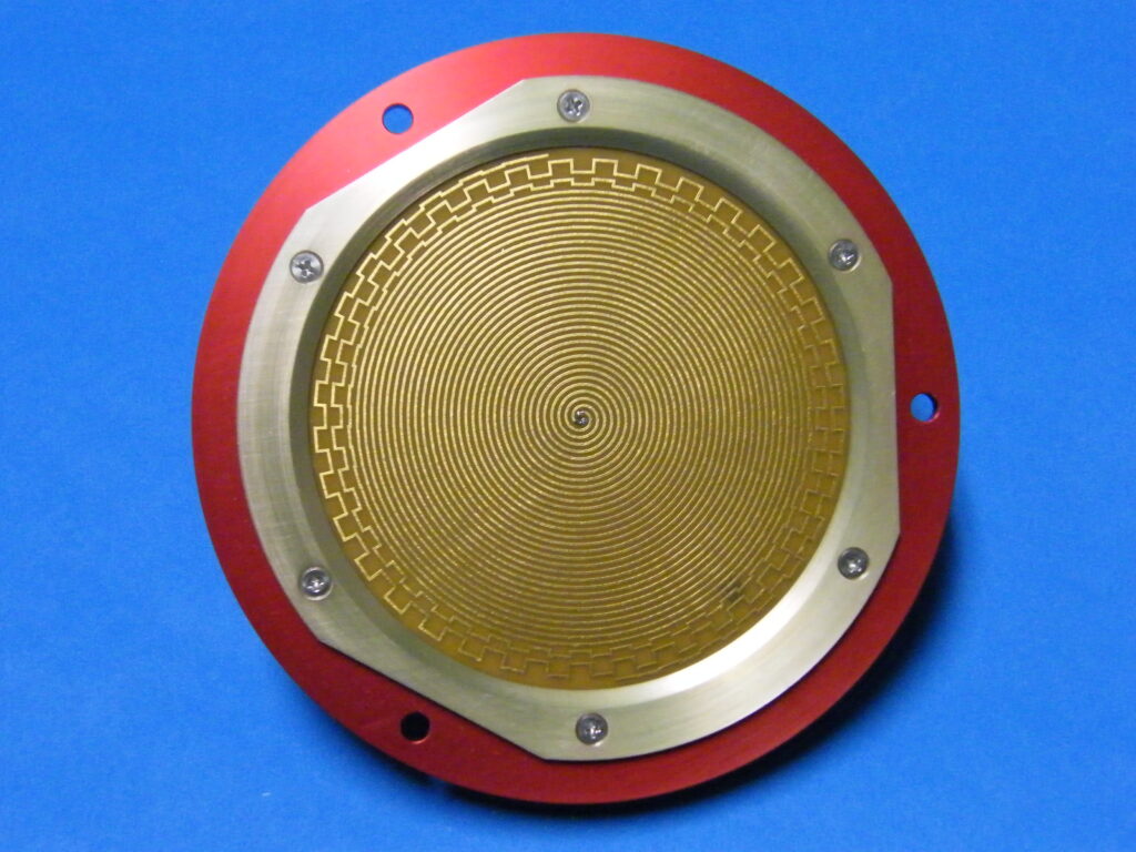
Spiral Antennas
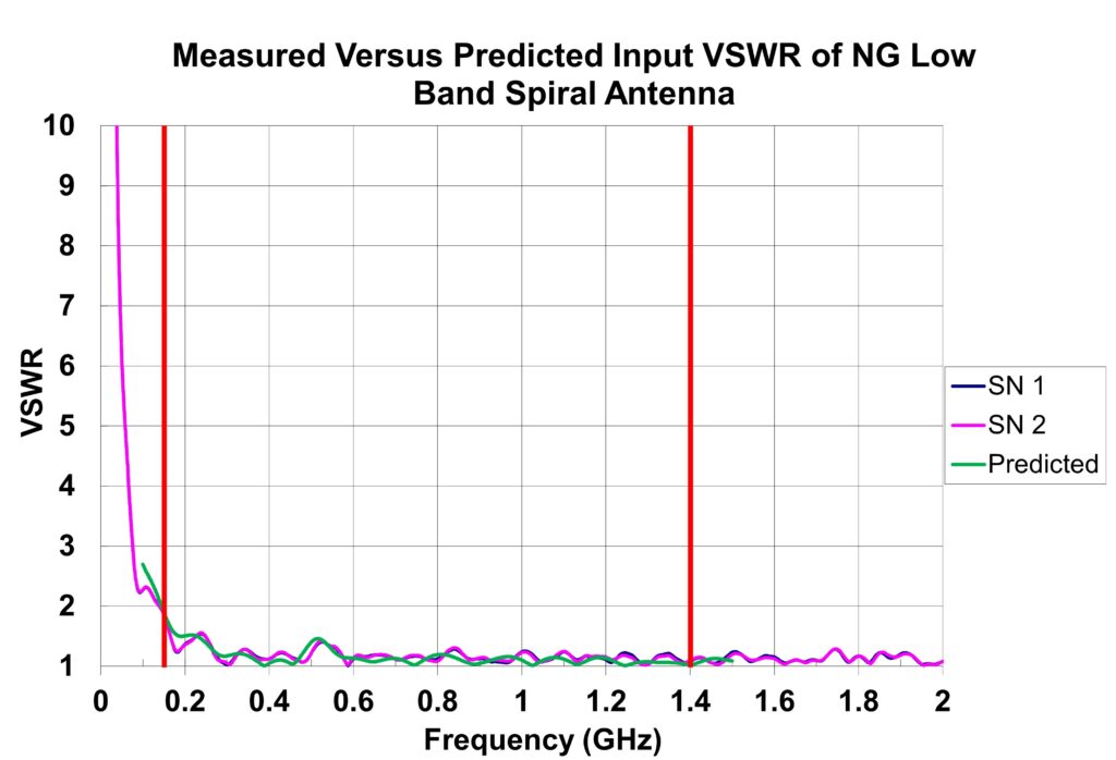
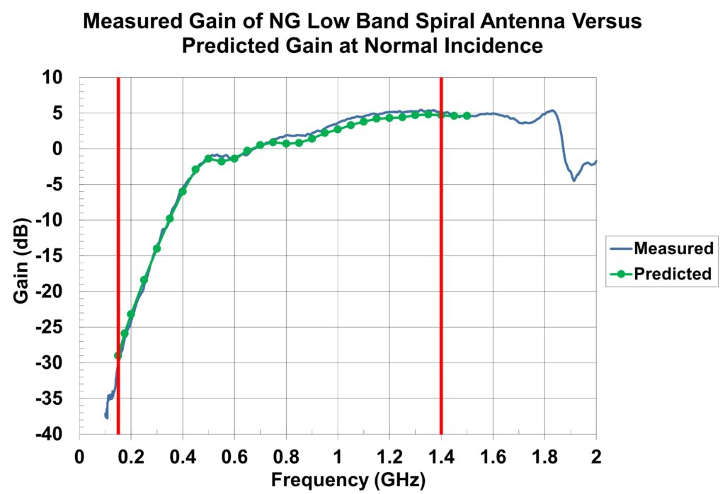
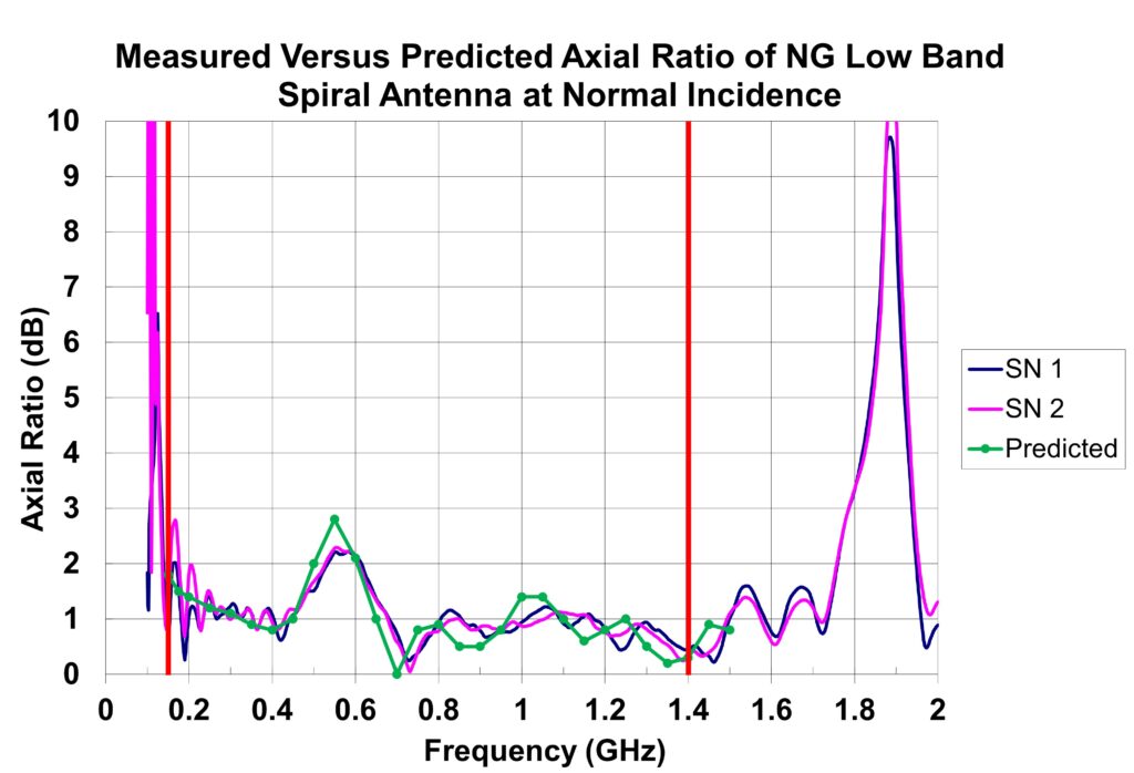
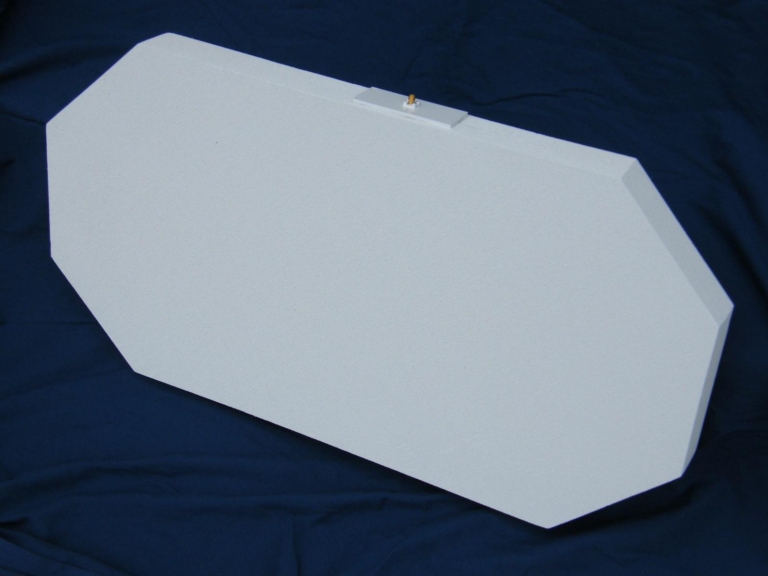
Broadband UHF Dipole Antenna
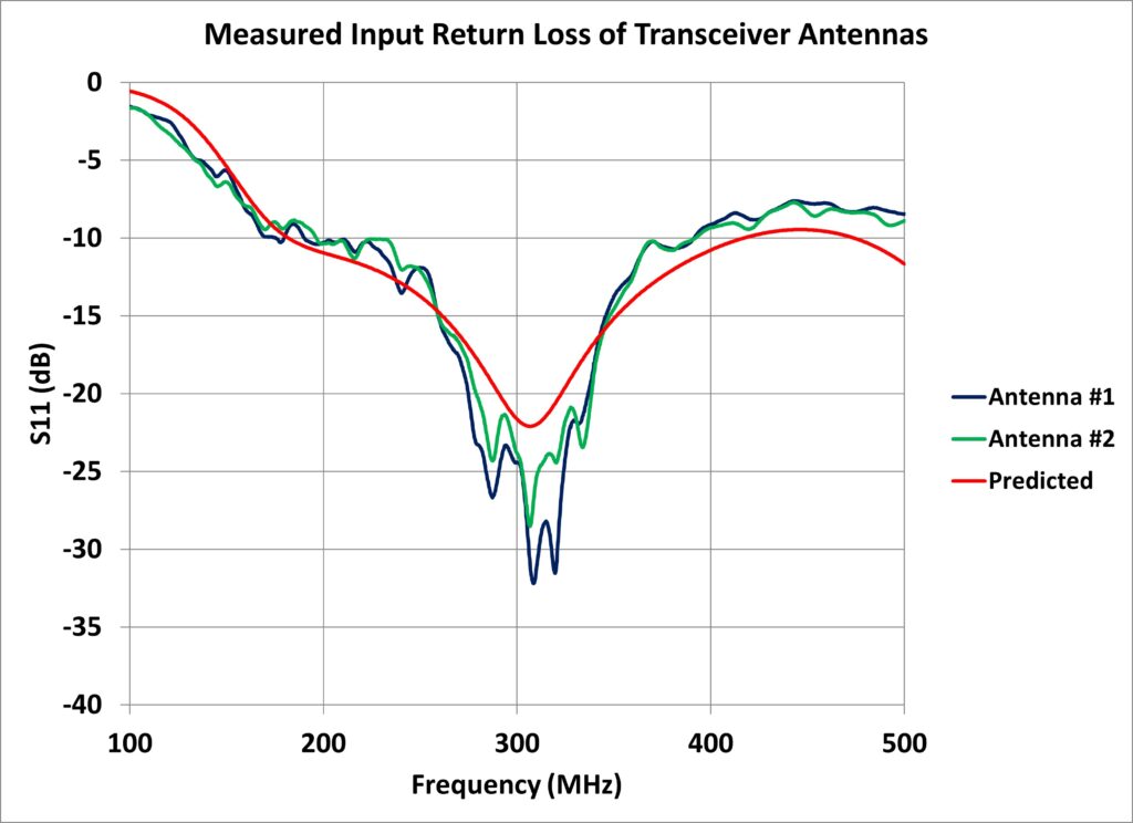
Broadband UHF Dipole Antenna Predicted and Measured Input Return Loss
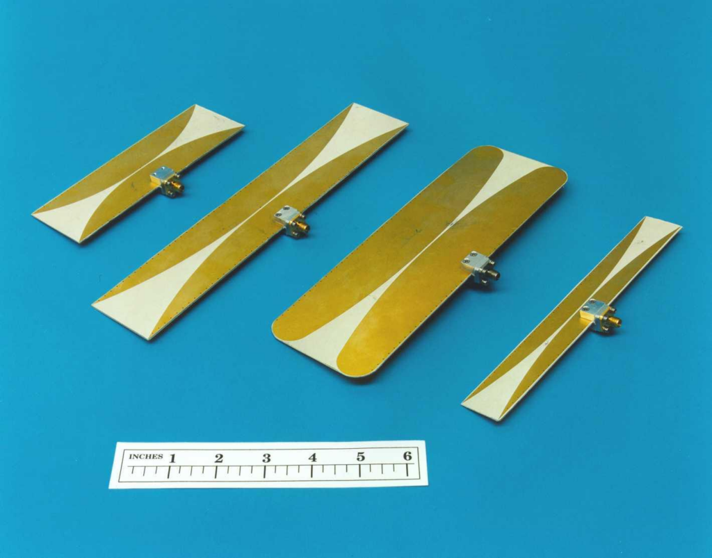
Broadband Notch Radiator Antennas – Individual Elements
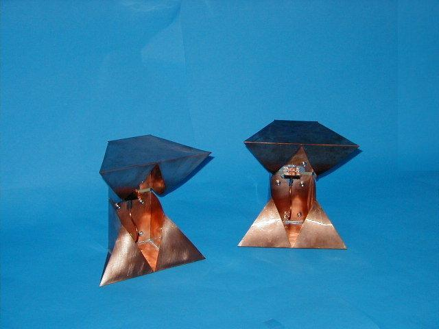
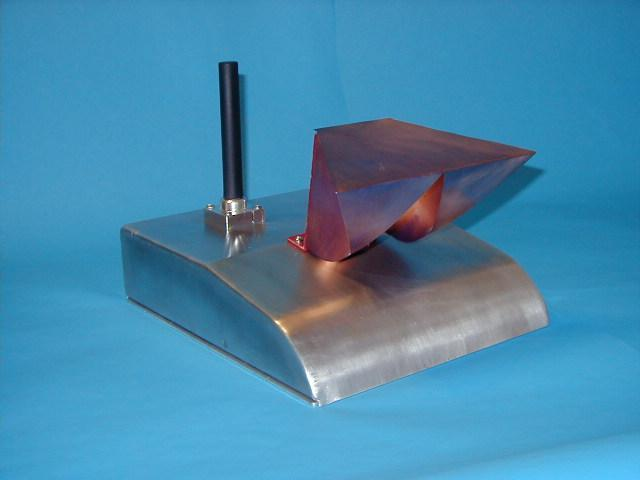
Multiband Communications Module with Enclosure
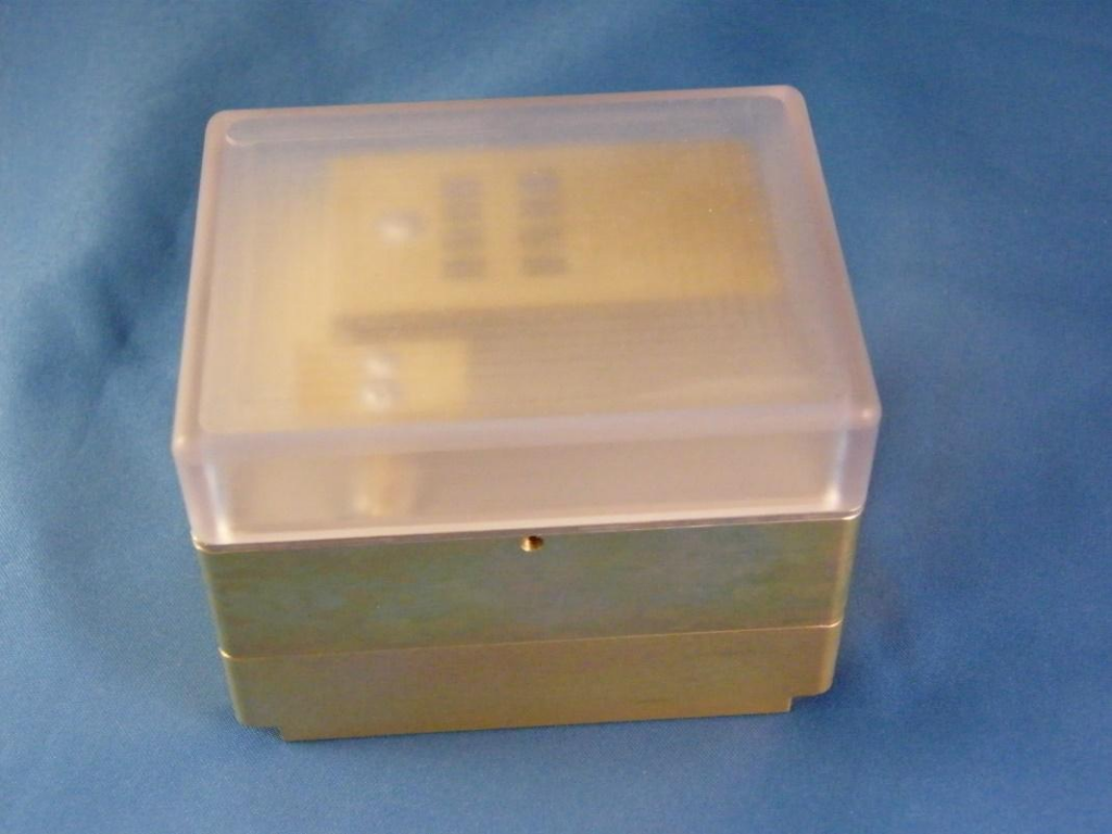

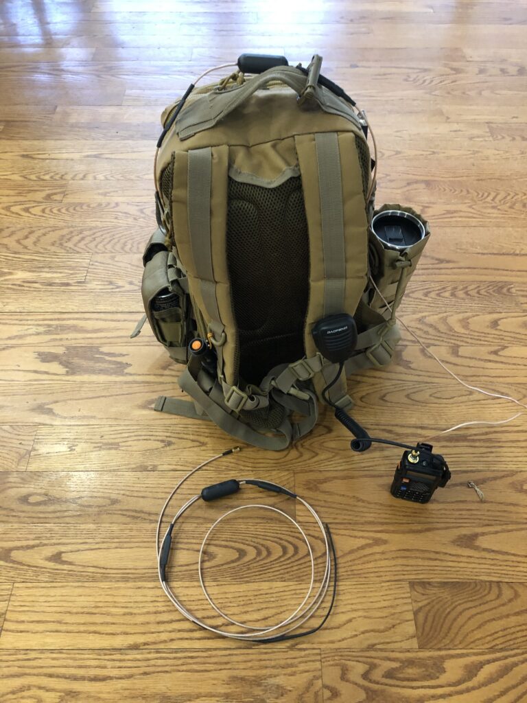
Embedded Antennas
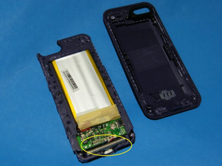
Embedded Antennas
30 – 80 MHz Tunable Loop Antenna
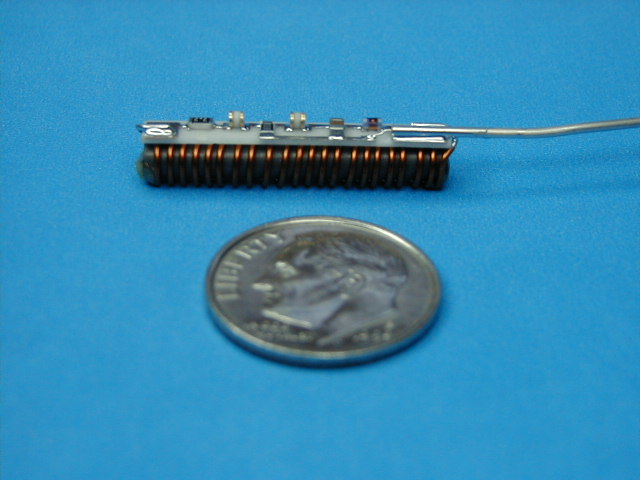
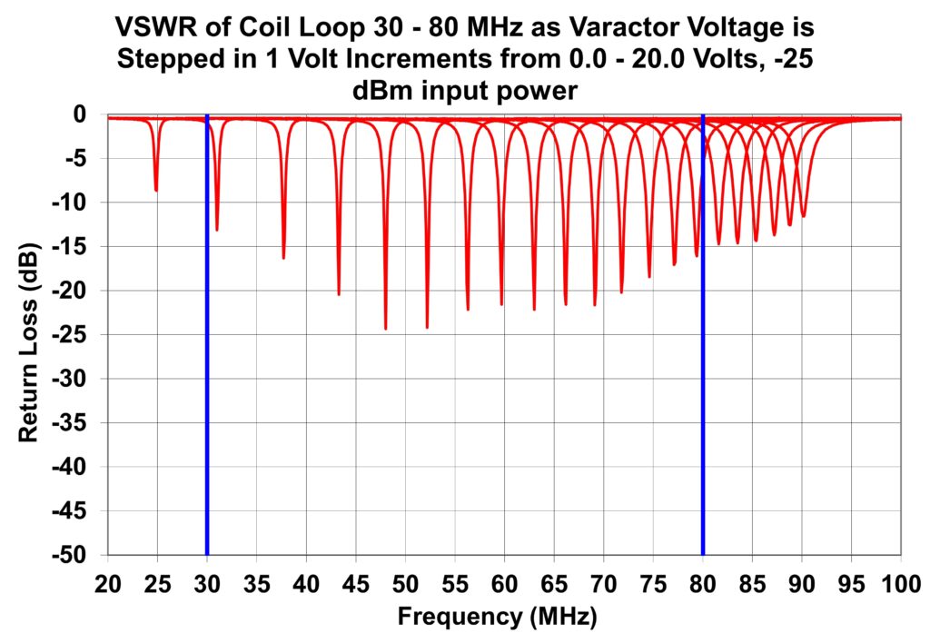
80 – 190 MHz Tunable Loop Antenna
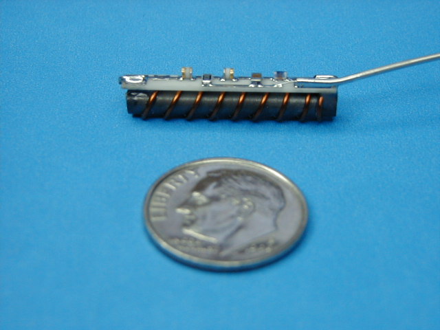
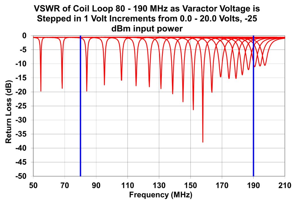
80 – 190 MHz Tunable Loop Antenna
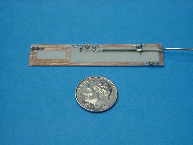
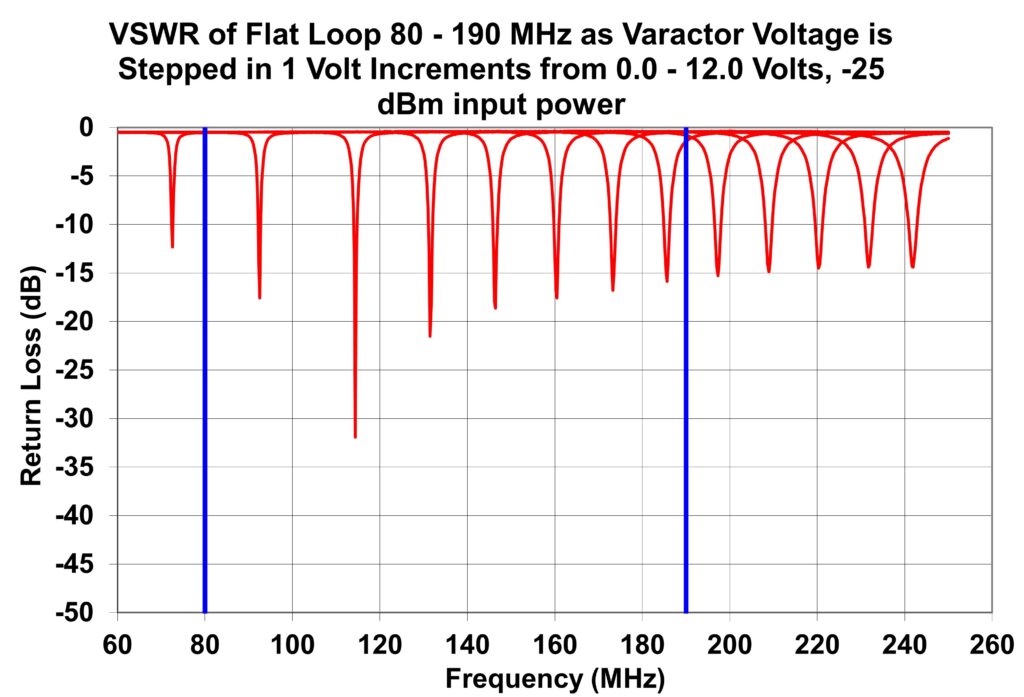
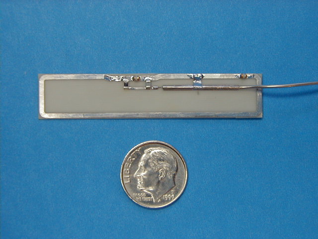
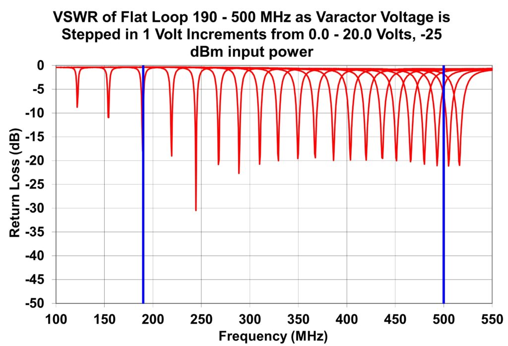
190 – 500 MHz Tunable Loop Antenna
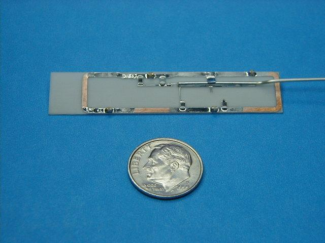
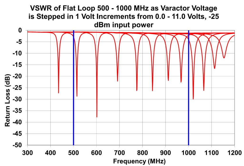
500 – 1000 MHz Tunable Loop Antenna
