Active Array Antenna Development
At Alpha Omega Electromagnetics, we have world class expertise in the development of high-performance antenna array technologies for both fixed beam and wide-scanning phased array applications. From space-based communication and radar systems to terrestrial and marine-based electronic warfare and direction-finding systems, at AOE we have the knowledge and expertise necessary to help you develop any kind of antenna product.
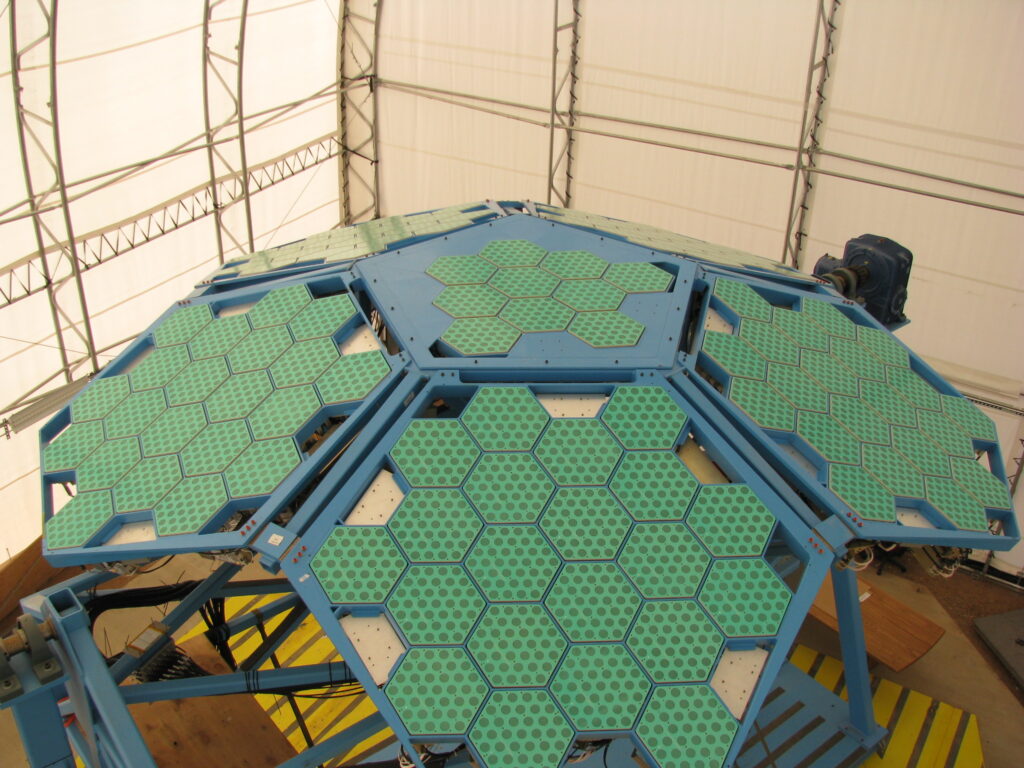
Geodesic Dome Phased Array Earth Station Antenna (GDPAA)
Development for the Air Force
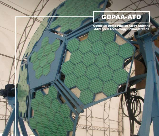
GDPAA Background
- Earth Station active array antenna developed for the Air Force for Tracking, Telemetry and Control (TT&C) of satellites for the Air Force Satellite Control Network (AFSCN)
- Proven technology and manufacturing approach, starts with TRL 9, MRL 9 radiator and adds digital elemental beamforming using all-COTS components
- Easily scales to address variety of LEO, GEO satellite missions
- 20+ Years Experience Designing and Building L/S active array subarrays
Performance Parameters for GDPAA Subarrays
| Parameter | Requirement |
| Uplink Frequency (SGLS transmit) | 1.764 – 1.842 GHz |
| Uplink Frequency (USB transmit) | 2.025 – 2.110 GHz |
| Downlink Frequency (receive) | 2.200 – 2.300 GHz |
| Operating Mode | Full Duplex |
| Coverage | Hemispherical |
| Transmit Beams | 1 |
| Receive Beams | 2 simultaneous |
| Polarization | RHCP, LHCP selectable |
| Axial Ratio | < 3 dB |
| VSWR @ feed | < 2:1 |
| Instantaneous bandwidth | > 20 MHz |
| Beam isolation within manifold | > 45 dB |
| Transmit power per element | 2 W |
Geodesic Dome Phased Array Earth Station Antenna Evolution
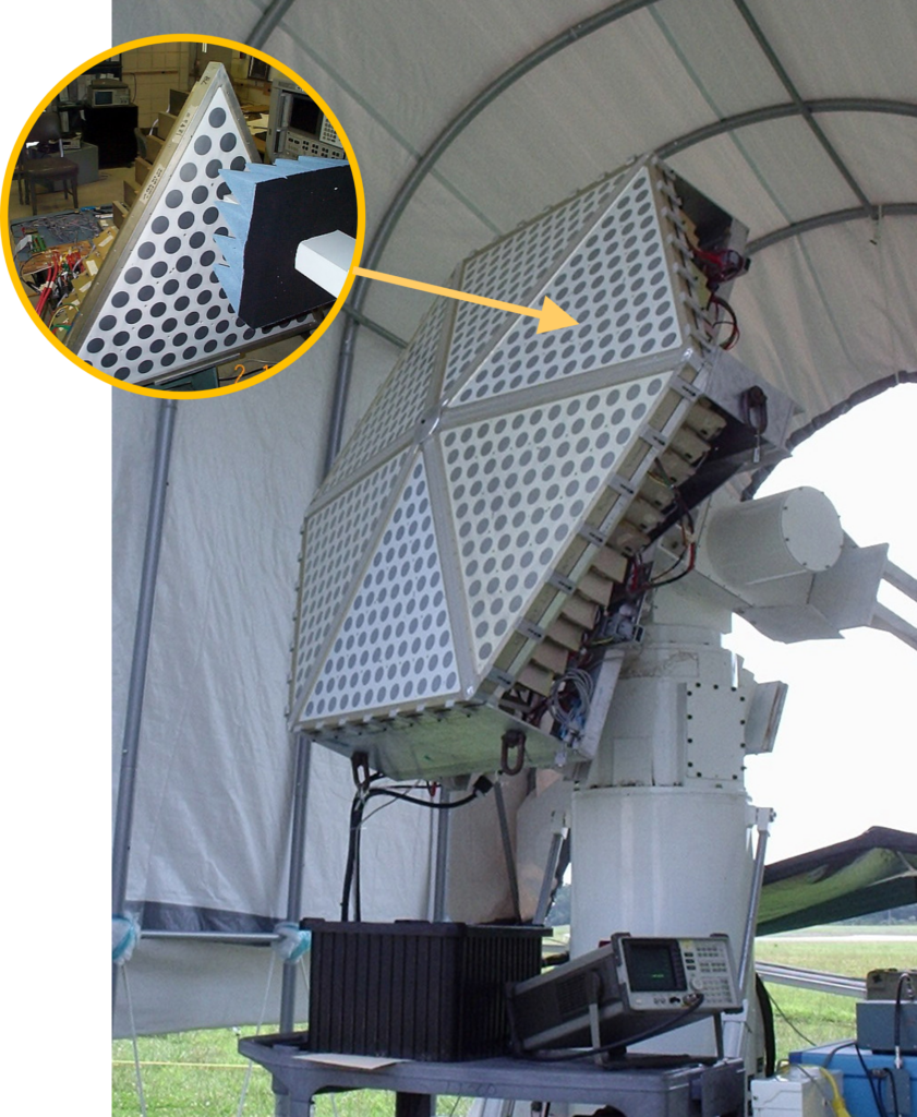
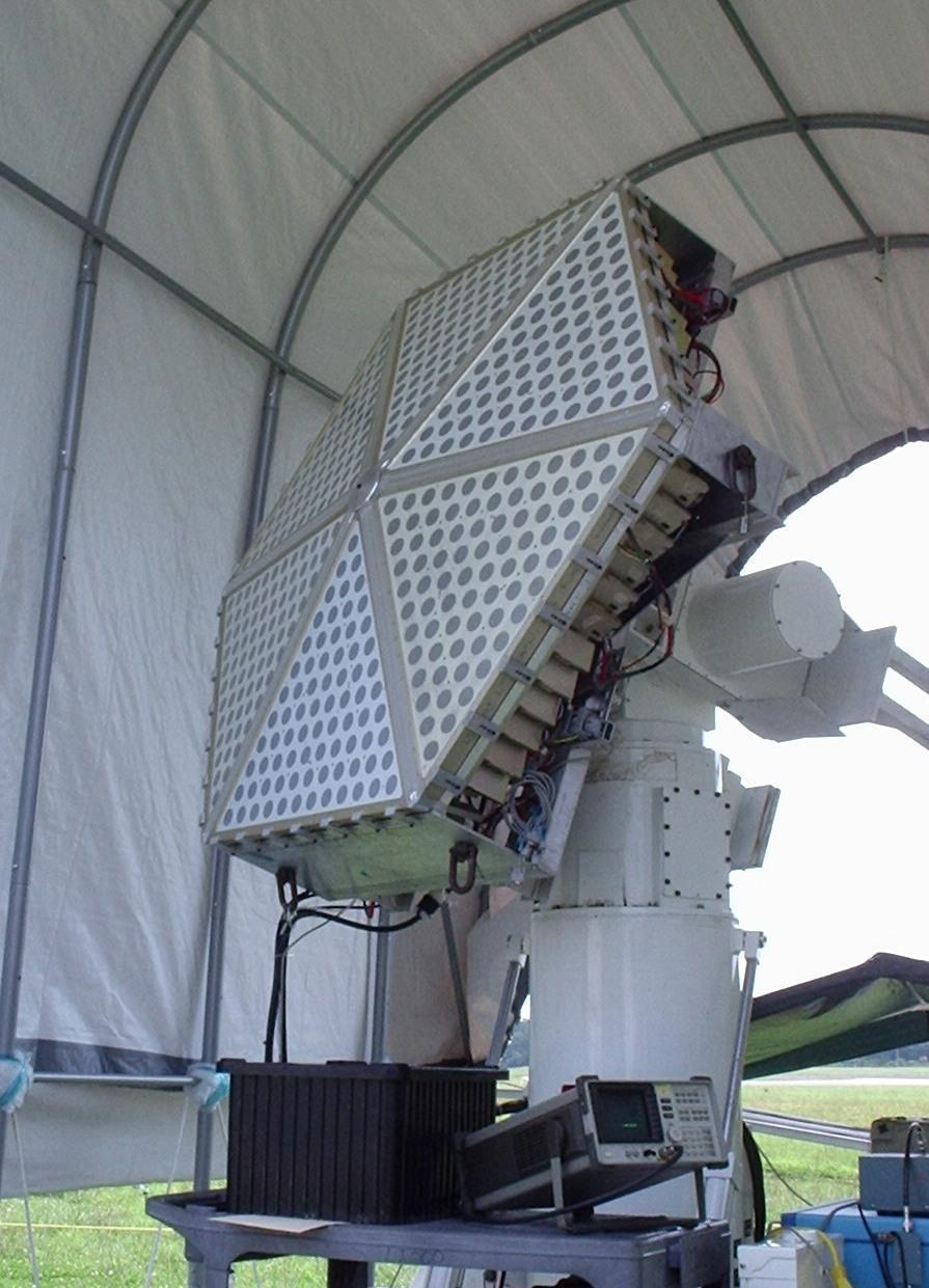
Air Force PAT DEMO w/ AOE Triangular Subarrays Gen 1, Brick Style: 2 Tx, 2 Rx simultaneous antenna beams
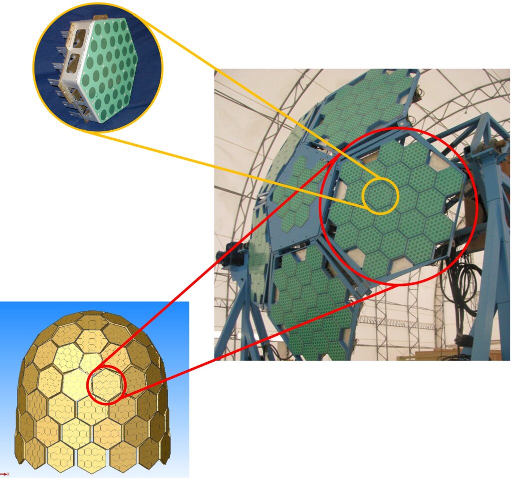
Air Force GDPAA ATD w/ AOE Hexagonal Subarrays Gen 2, Brick Style: 1 Tx, 2 Rx simultaneous antenna beams
AOE Planar Array Architecture Offers Substantial Savings in ALL Elements of SWAPC
Parameter | Previous Subarray | AOE Planar Subarray | Savings |
Cost/Subarray | $19,082 | $7,634 | 60% |
Cost/Element | $530 | $212 | 60% |
Volume | 2155 cu in | 455 cu in | 79% |
Depth | 7.1” | 1.5” | 79% |
Weight | 50 lbs | 15 lbs | 70% |
Prime Power | 432 W | 213 W | 51% |
Req. Cooling | 360 W | 141 W | 61% |
Advanced Space Antenna for GPS
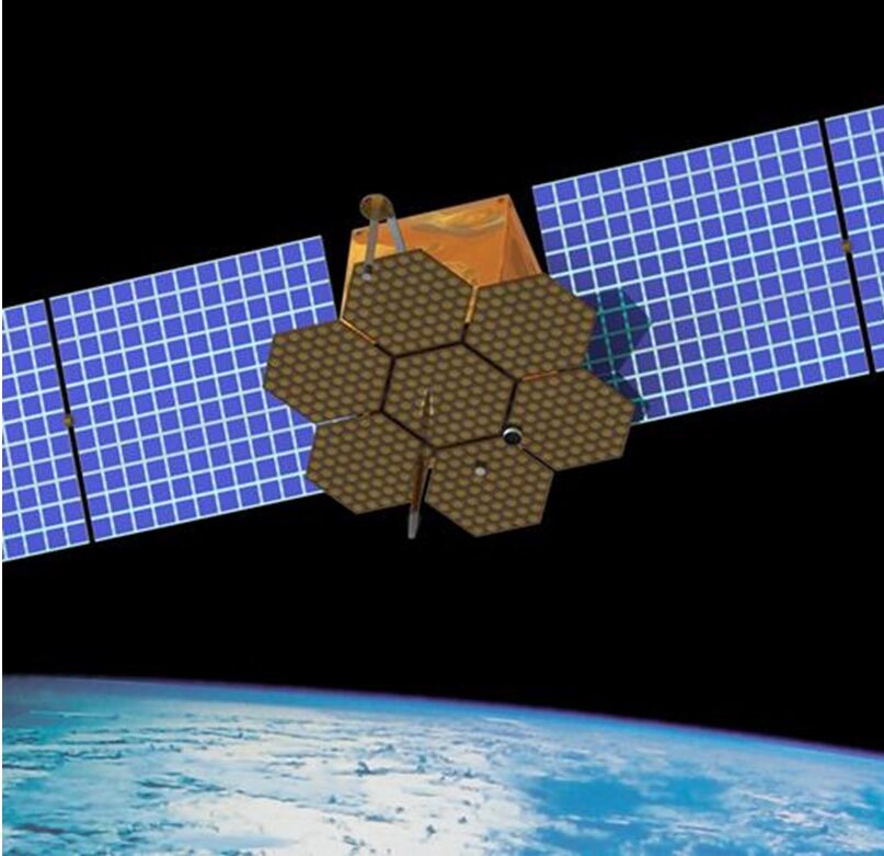
One panel of an Advanced Space Antenna for GPS developed under an Air Force SBIR program that provides 3 independent Tx antenna beams with simultaneous earth and spot beam coverage.
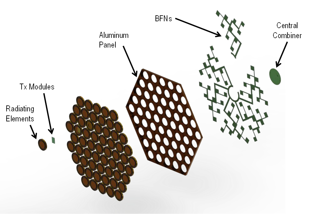
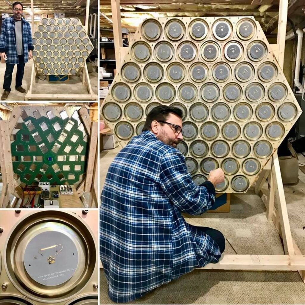
| Parameter | Threshold | Objective |
| Transmit Frequencies (L1, L2, L5) | 1575.42 MHz, 1227.60 MHz, 1176.45 MHz | Same as threshold |
| Bandwidths (L1, L2, L5) | 45 MHz, 20 MHz, 20 MHz | 45 MHz, 45 MHz, 20 MHz |
| Transmit Power per Beam (L1, L2, L5) | 250 W, 110 W, 90 W | 400 W, 150 W, 150 W |
| Antenna Patterns | L1, L2, L5 – 14° Half-Angle Earth Coverage L1, L2 – 4° Wide Flat-Topped Spot | Threshold in addition to superposition of Earth Coverage and 4° Spot |
| Antenna Gain | 15 dBiC Earth Coverage 25 dBiC Flat-Topped Spot | 15 dBiC Earth Coverage 27 dBiC Flat-Topped Spot |
| Operating Mode | Continuous | Same as threshold |
| Coverage | 14° Half-Angle Cone | Same as threshold |
| Transmit Beams | L1, L2 Simultaneous, Independent, L5 Fixed | 3 Simultaneous, Independent |
| Polarization | Right Hand Circular | Same as threshold |
| Axial Ratio | < 3 dB | < 1 dB |
| VSWR @ Feed | < 2:1 | Same as threshold |
| Total Ionizing Dose | 1×10⁶ rad(Si) | Same as threshold |
| Single Event Upset | 1×10⁻¹⁰ err/bit-day | Same as threshold |
| Single Event Latchup | None | Same as threshold |
| Dose-Rate Upset | 1×10¹⁰ rad(Si)/s | Same as threshold |
| Dose-Rate Survivability | 1×10¹² rad(Si)/s | Same as threshold |
Broadband, Space-Based Active Array Antenna Tile
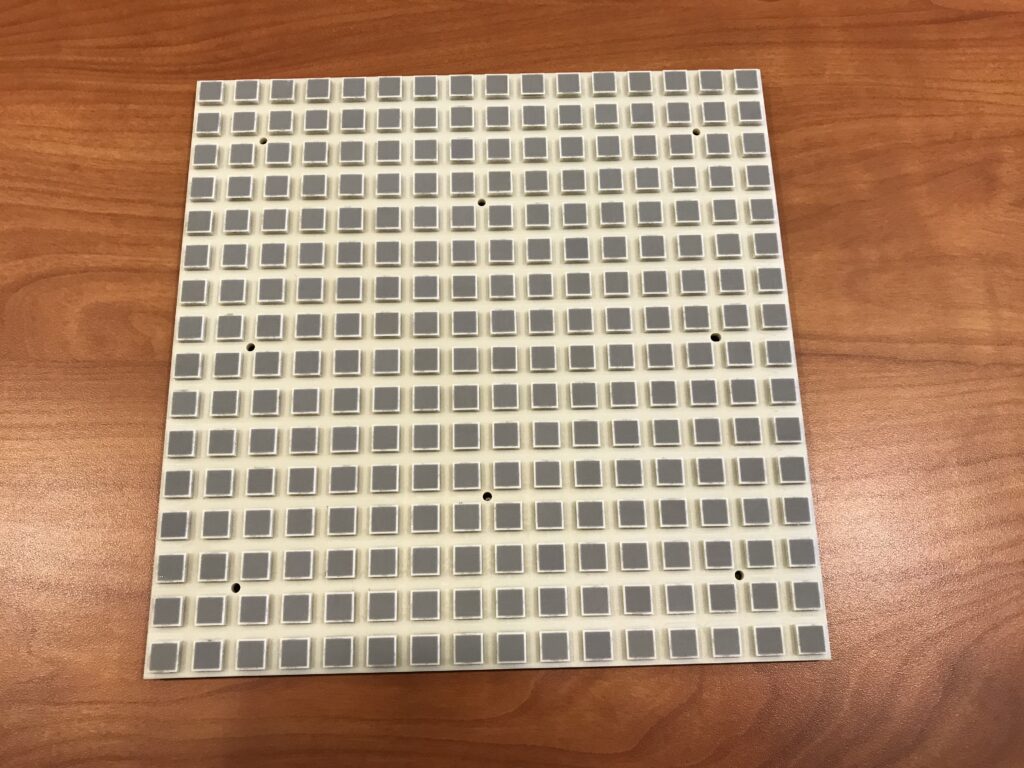
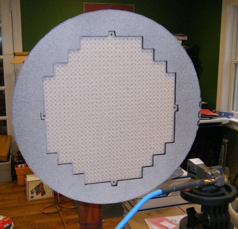
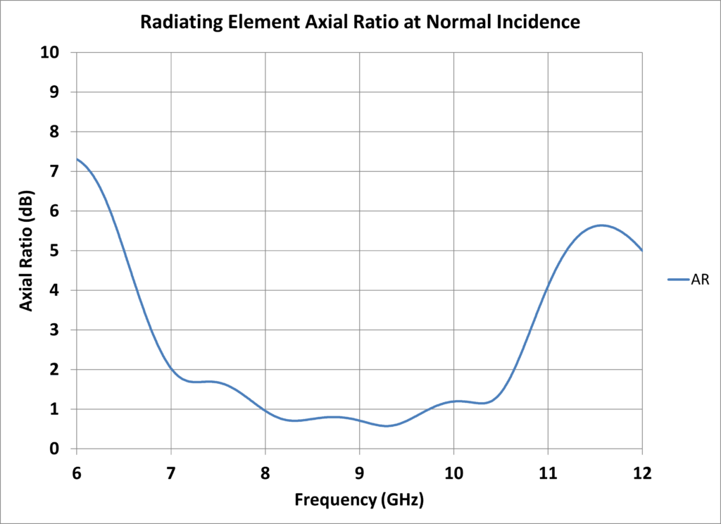
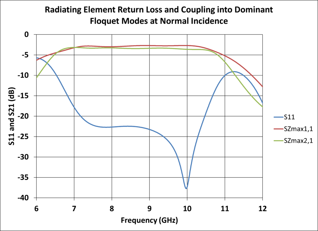
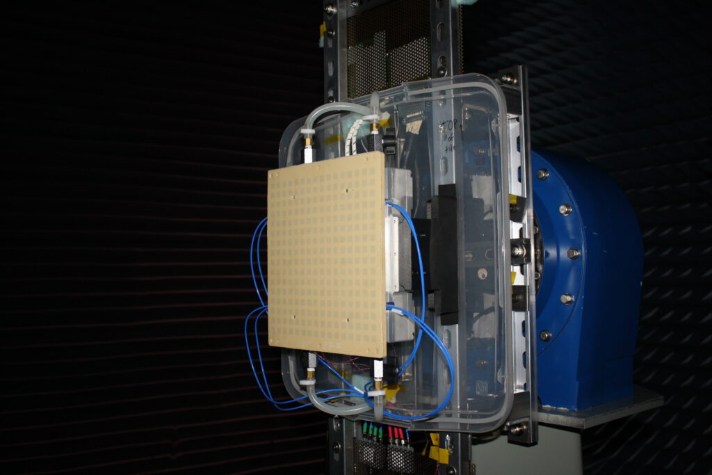
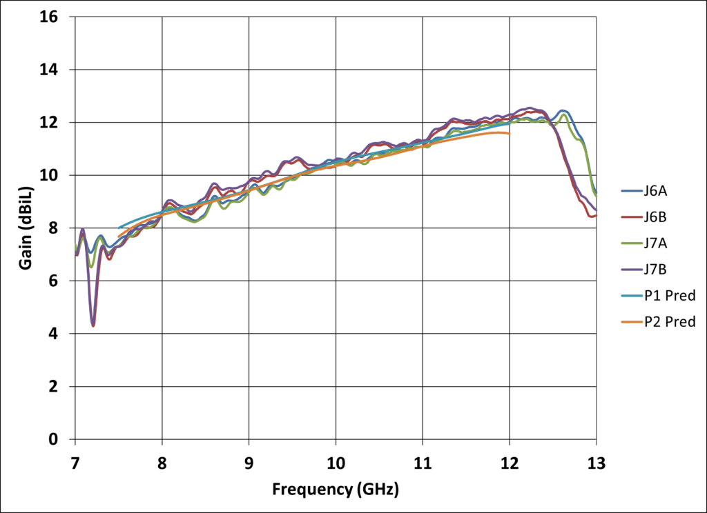
X-band, broadband (7.5 – 12 GHz), dual-polarized active array antenna tile developed for a space-based radar application.
Predicted and measured gain of X-band, broadband (7.5 – 12 GHz), dual-polarized active array antenna tile
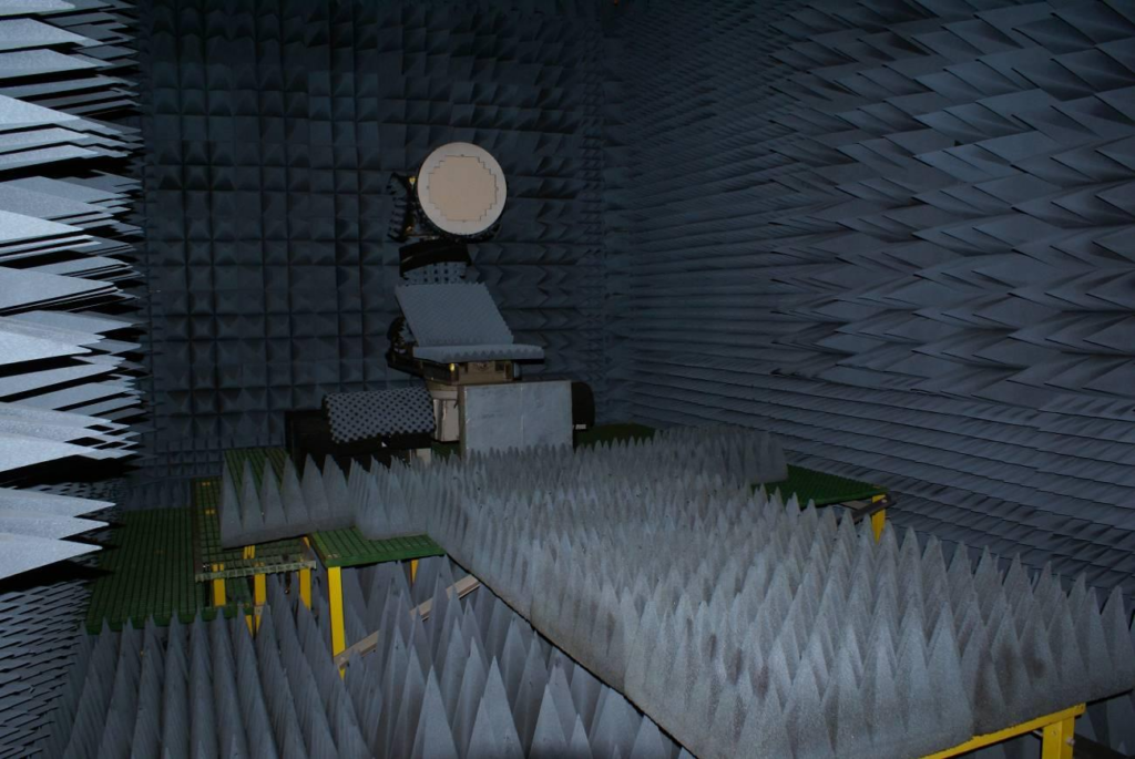
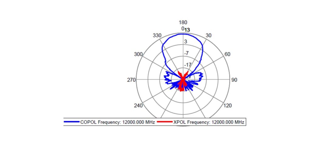
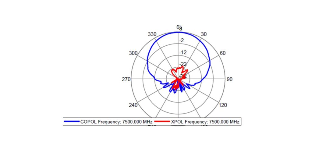
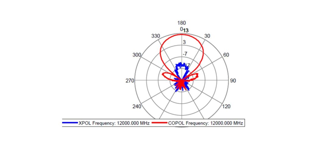
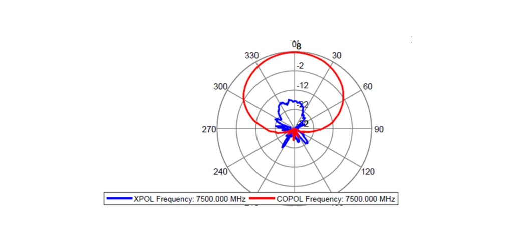
Measured antenna patterns of 2×2 element clusters of X-band, broadband (7.5 – 12 GHz), dual-polarized active array antenna tile
7 – 12 GHz Active Receive Only Antenna Tiles
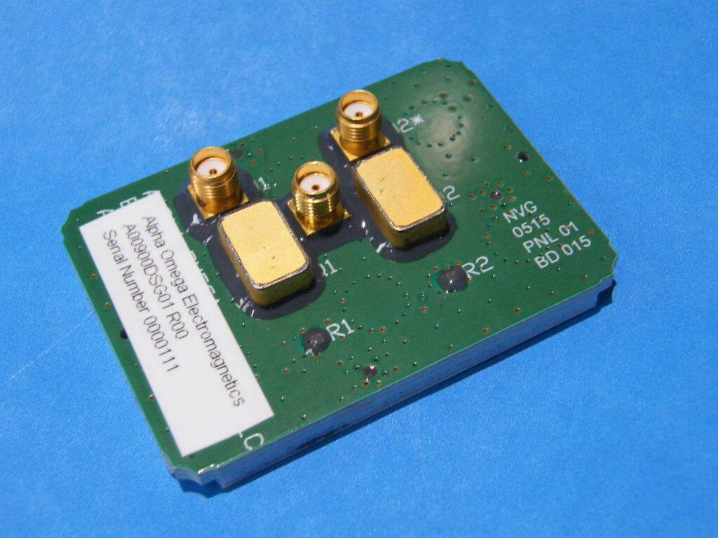
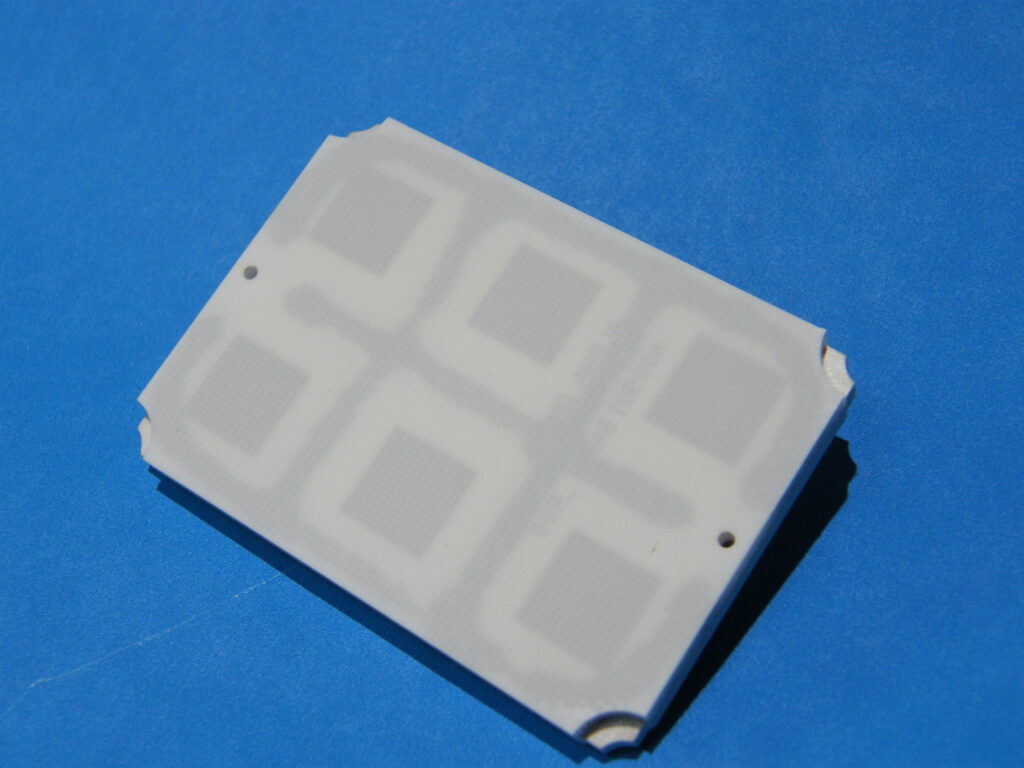
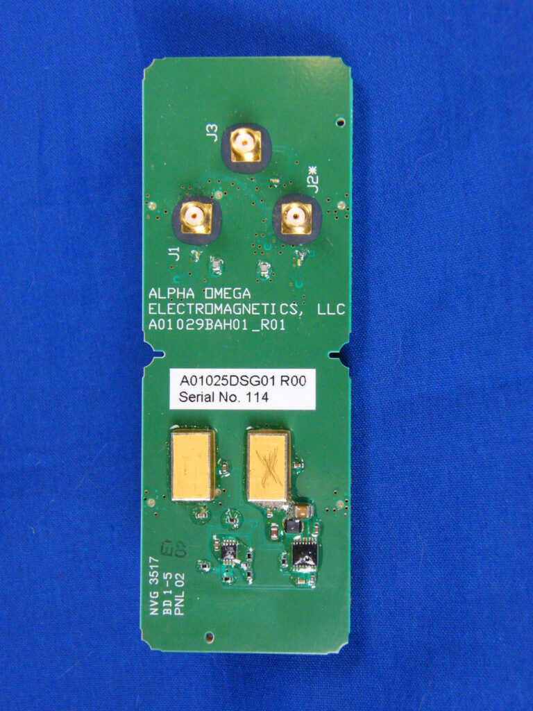
- Developed for a high-power, airborne radar application
- Simultaneous dual linear polarization operation with high isolation between polarizations
- Proven technology with 3 generations developed and flown
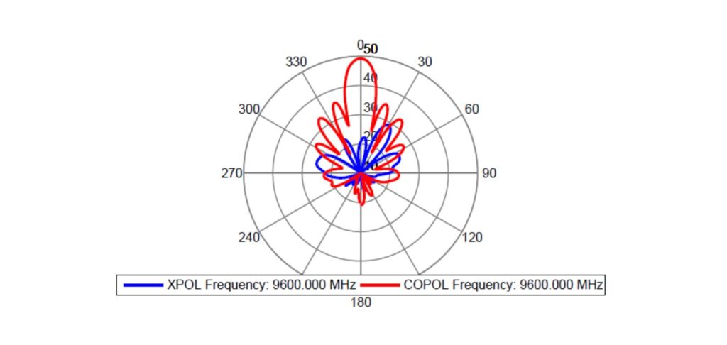
Table 1. X-band Receive Antenna Tile requirements and predicted performance.
Parameter | Requirement | Predicted Performance |
Operating frequency | 7.0 – 12.0 GHz | > 7.0 – 12.0 GHz |
Peak input power to limiter | 80 W | > 100 W |
Maximum average power input to limiter | 4 W | 6 W |
Amplifier input level for 1 dB output compression | >-19 dBm peak, >-17 dBm average, measured from 7-12 GHz in 1 GHz steps | Compliant |
Amplifier minimum gain | 30 dB | >30 dB |
Noise figure, antenna input to SMA output connectors) | < 3.8 dB | 3.8 dB @ 25°C, 3.3 dB @ -40°C |
Tile thickness (not including connectors) | < 0.5” | Compliant |
Shock and vibration | Per RFQ | Per RFQ |
Polarization | Dual linear, V and H | Dual linear, V and H |
Polarization isolation | > 20 dB | > 20 dB |
Operating temperature range | -60°F to 120°F (-51°C to 49°C) | Compliant |
3 dB azimuth beamwidth @ 9.5 GHz | 35° | 35° +/- 1° |
3 dB elevation beamwidth @ 9.5 GHz | 12.5° | 12.5° +/- 1° |
Mounting | Mounting as specified | Compliant |
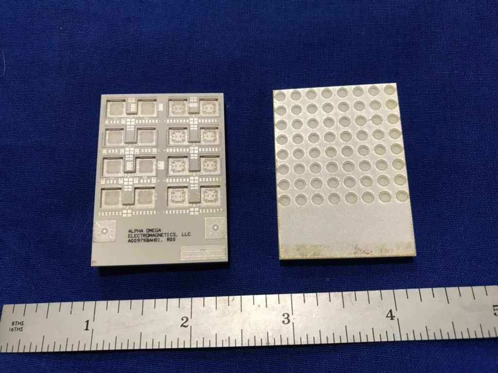
Ka-Band LTCC-Based Array Antenna Tiles
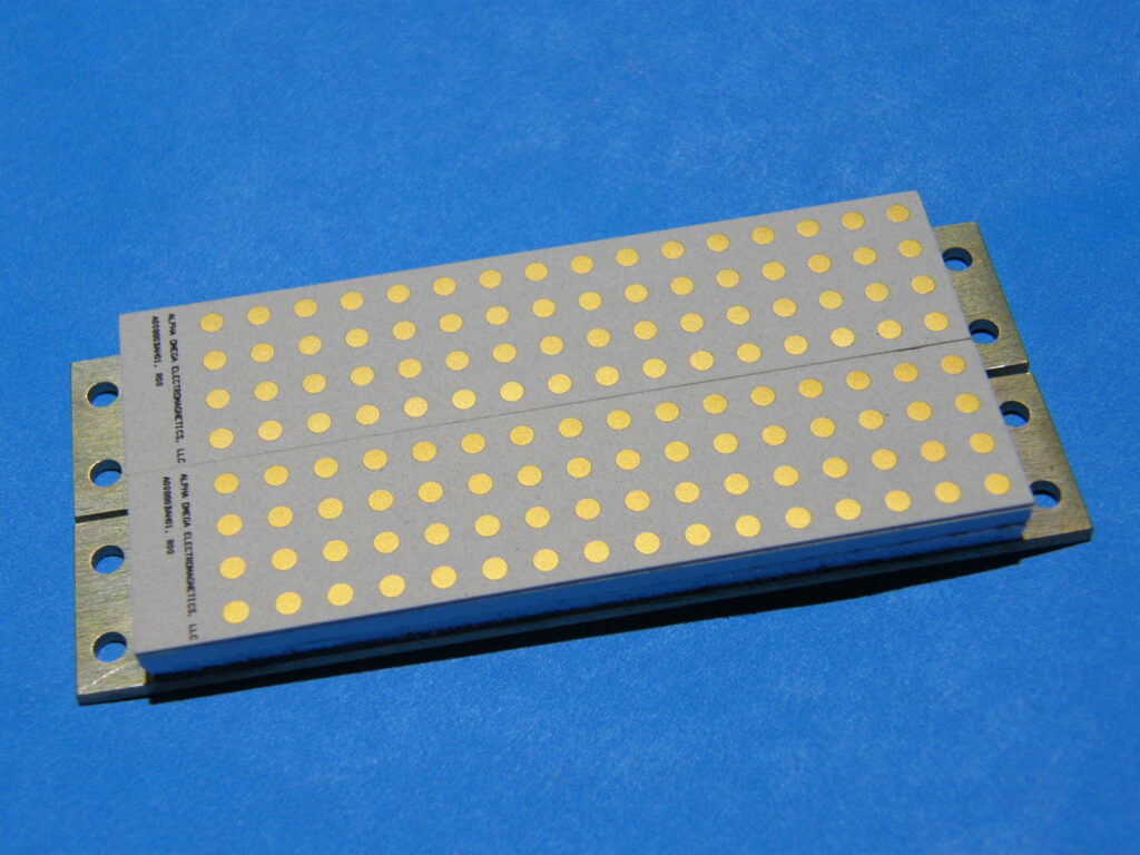
- Developed for a high-power Ka-band radar application
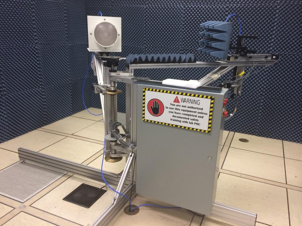
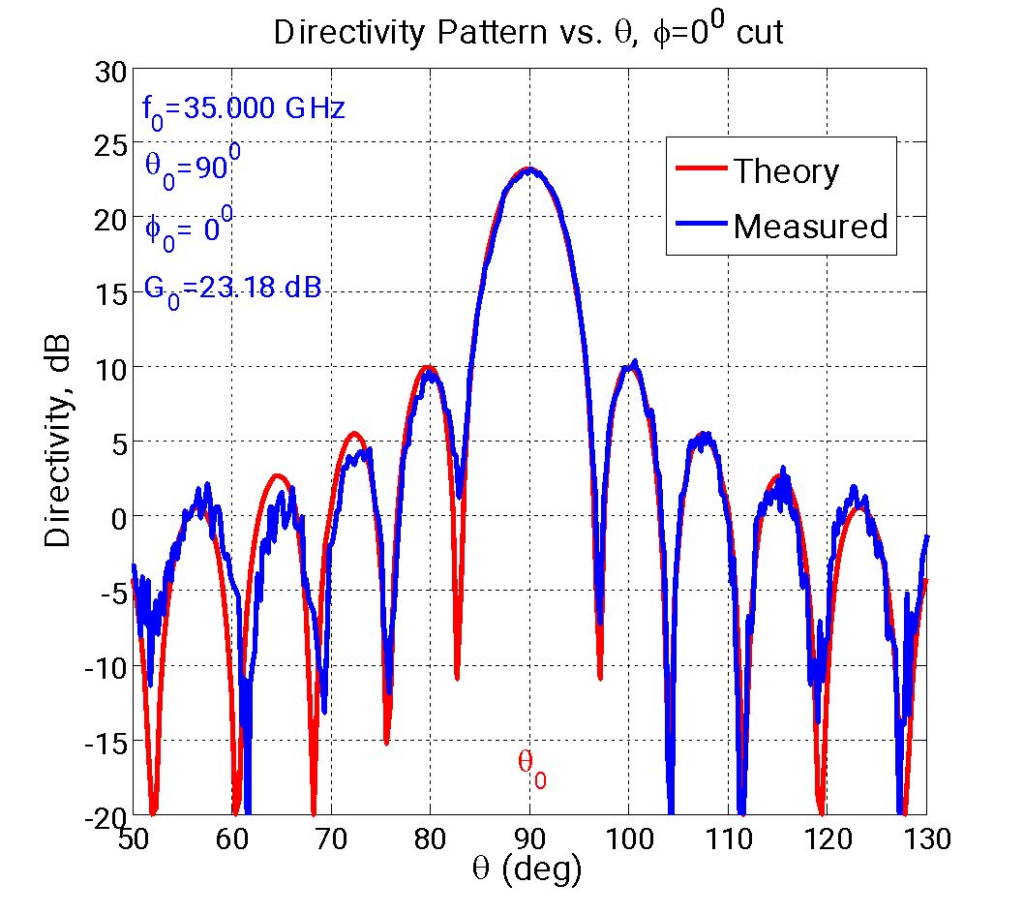
- Incorporates broadband, circular polarized radiating aperture
- Integrated liquid cooling channels
Advanced Space-Based, Electronically Steerable, Deployable, Dual-Band Reflect Array Antenna for GPS
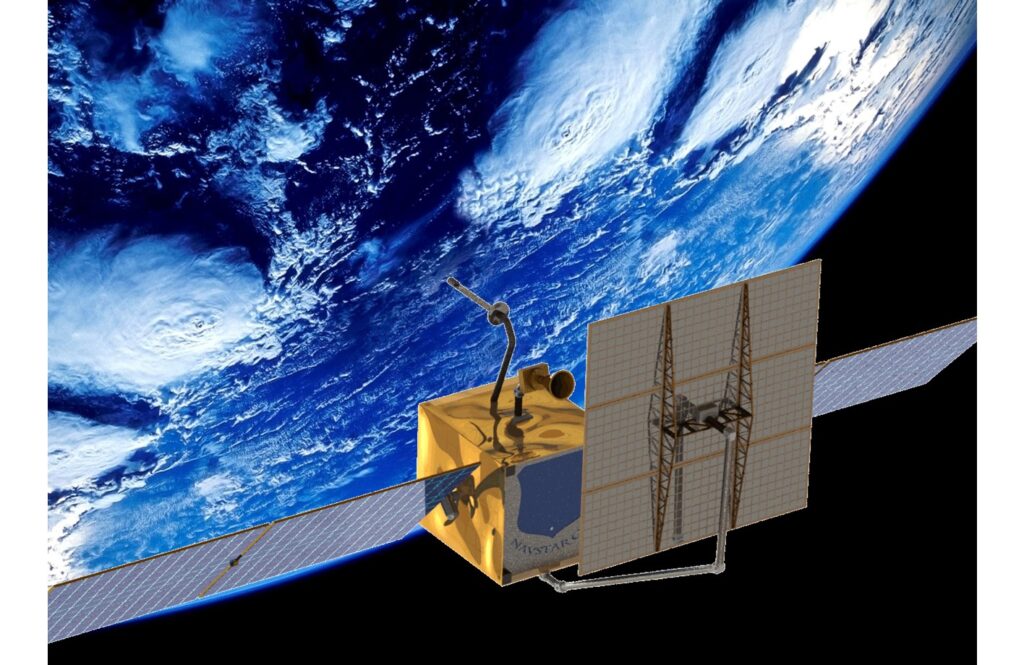
- Yields simultaneous high gain transmit beams at L1 and L2 frequencies
- Allows for simultaneous operation of legacy Earth coverage antenna beams
- Incorporates low-loss phase shifters developed by AOE to independently, electronically steer the high gain beams
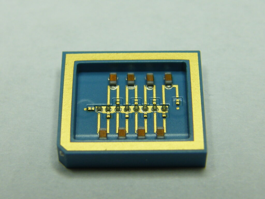
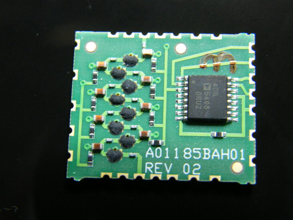
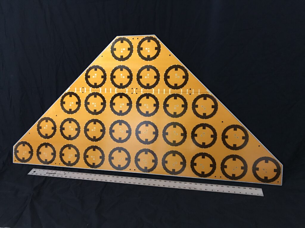
Low-Loss Phase Shifters Developed for AOE’s GPS Reflect Array
High Performance Passive Patch Antenna Arrays
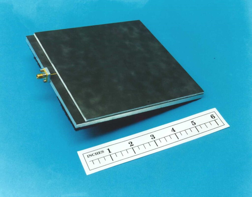
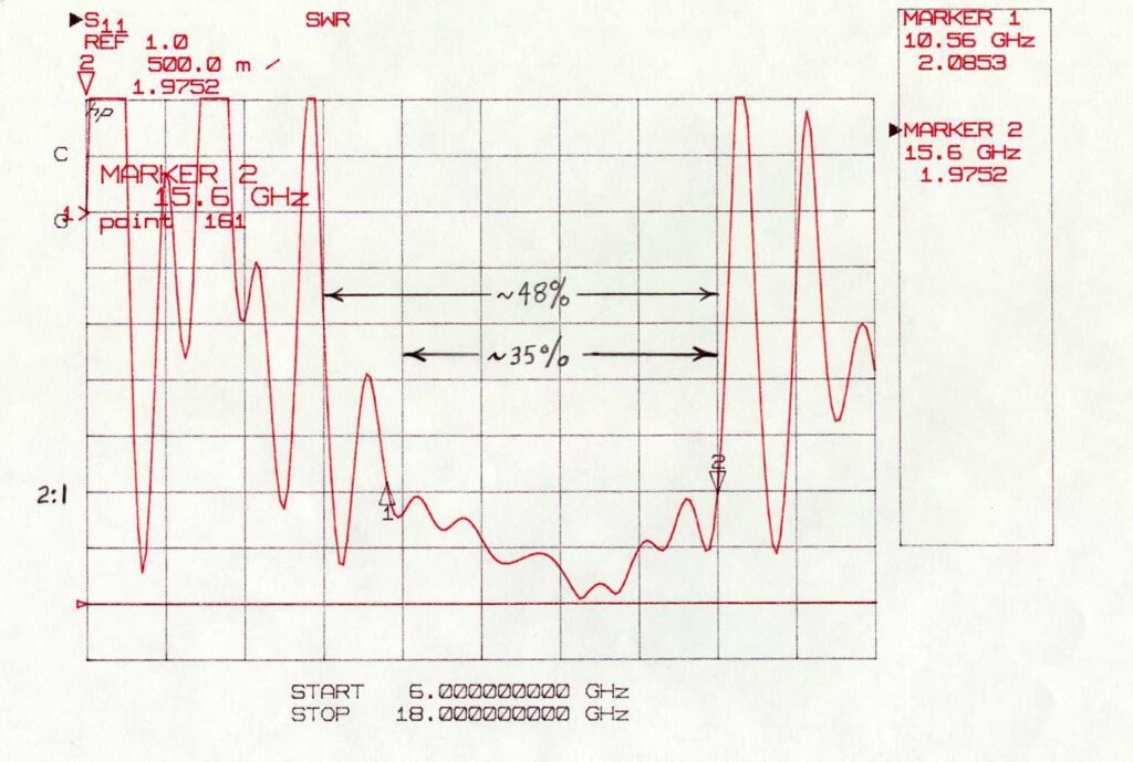
Aperture-Coupled Stacked Patch Array
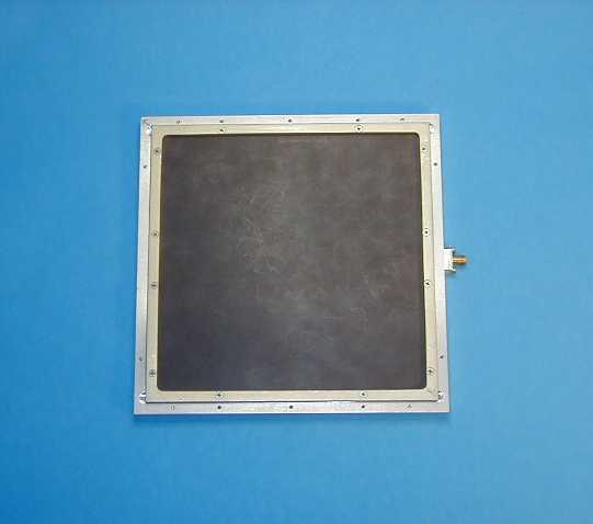
Proximity Coupled Stacked Patch Array

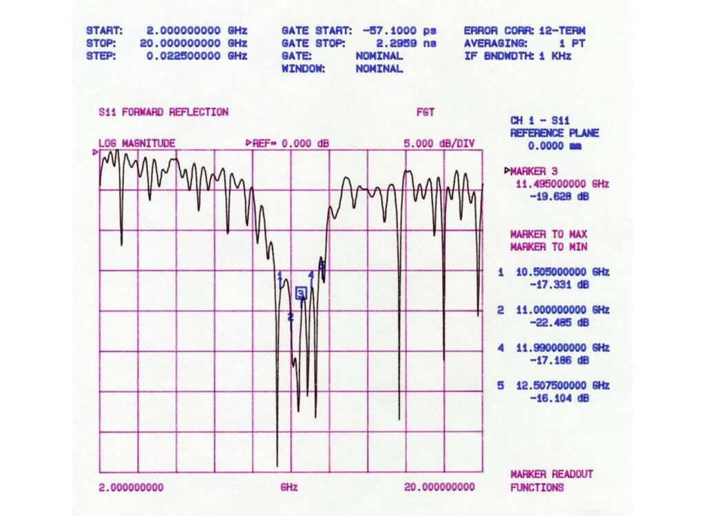
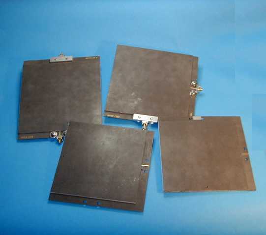
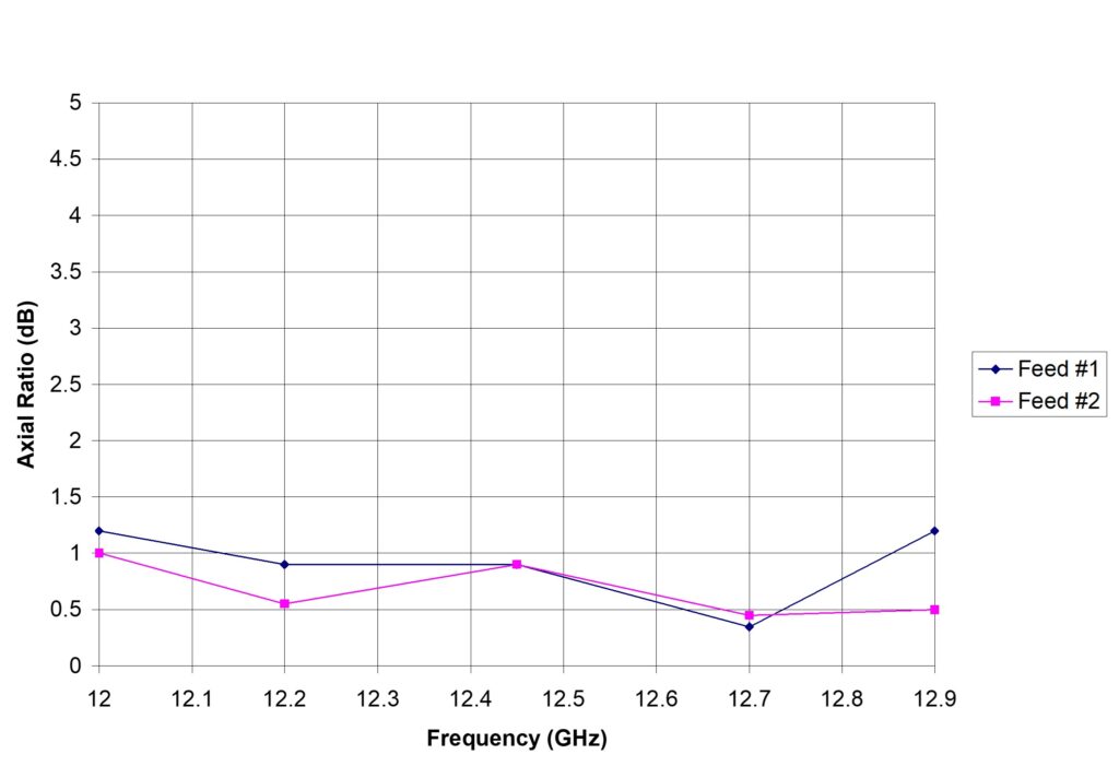
Dual Circular Polarization DBS Antenna
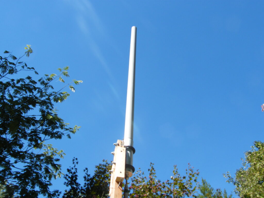
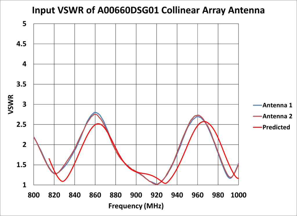
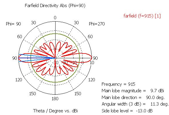
Collinear Dipole Array

Parameter | Requirement |
Operating Frequency | 902 – 928 MHz |
Input VSWR | <2:1 |
Gain | >8 dBi |
Polarization | Linear, Vertical |
H-plane Pattern | Omnidirectional |
E-plane 3 dB Beamwidth | 14° |
Maximum Input Power | 10 W |
Input Impedance | 50 Ω |
Dimensions (Height x Diameter) | 53” x 2.5” |
Weight | <2 lbs |
Input Connector | N Female |
Mount | 2.5” Pole Mount |
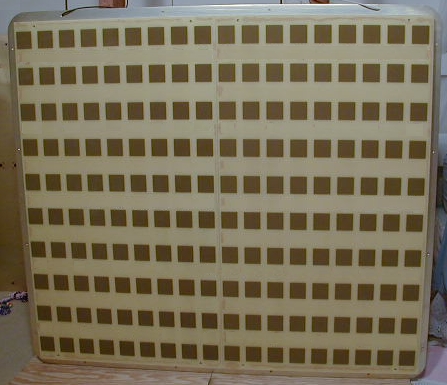
Smart Antenna Aperture Design for MMDS Band
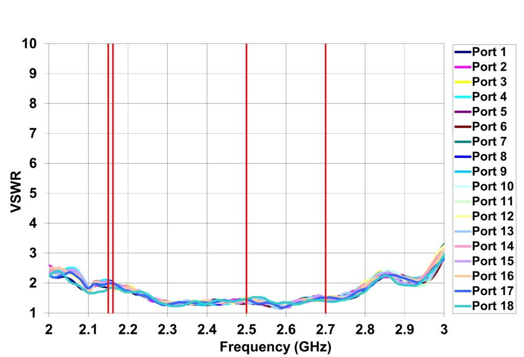
Dual-Beam, K-Band Space-Based SATCOM Antenna
